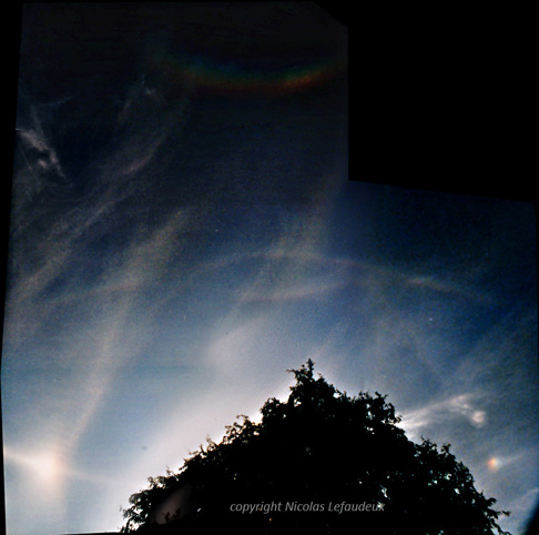
Last weekend, I visited my parents in Normandy. I took advantage of my visit to dig through my old astronomy journals of observations and pictures. I was looking for my records of what has been my best halo display. In my memories, it consisted in extremely bright left parhelion, bright circumzenithal, and a combination of suncave Parry and upper tangent arc.
I found my record, sketch ( <a href=" http://www.ursa.fi/blogit/media/blogs/halos/Lefaudeux/18-09-98-17h15-17h55HL_post.jpg">1 ) and pictures ( 2 - 3 - 4 ), and realized there were very prominent Lowitz arcs too!
From my notes, the display happened on September 18th, 1998, between 17h15 and 17h55 local time. The sun was at 24 degrees altitude at the middle of the display. At that time, I had little knowledge of the halos. I just knew from astronomy books about parhelia, 22° and 46° halos. I had observed before upper tangent arc (which I called upper 22° parhelion) and circumzenithal arc (which I called upper 46° parhelion), but never Parry arc.
During the display, I was mesmerized by the colourful upper suncave parry arc and by the parhelion brightness. My notes are focused on these arcs, especially the Parry one, with detailed description of its length, width, brightness and colors. Nothing on the Lowitz arcs except the sketch which shows radiating arcs from parhelia.
The stitched picture shows almost complete upper Lowitz arc, very long Parry arc and faint 22° halo. There are also some weird bands on the bright parhelion. I think I have some memories of shadow bands running across the parhelion, a bit like in the video by Anna Herbst ( <a href=" http://spaceweather.com/swpod2010/11feb10/anna-herbst1.mov?PHPSESSID=liolll4f05nuq4m9ascc45gpg5">5 ), but cannot be sure as there is no mention of these in my notes.
I really wish I could observe again such an exceptional display now that I am able to appreciate it to its true worth
Nicolas Lefaudeux
Thursday, 22 April 2010
Tuesday, 13 April 2010
An animated stereo simulation of streetlight halos
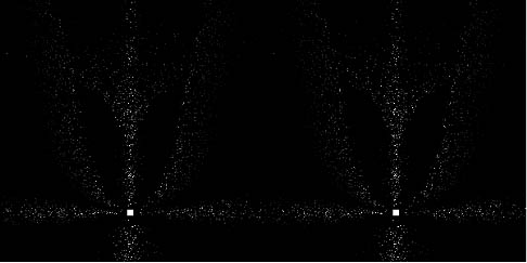
I suggest the following explanation: The ice crystal halo display is not made simply from idealized halo surfaces (or, more general, from an intensity field in space which takes into account all the subtle intensity variations along parhelia, tangent arcs, and so on) rather than from individual crystals that fall down or drift around in space and sample the intensity field pointwise along their trajectories. These crystals are real physical objects and should be perceived stereoscopically at their actual position, if being illuminated externally at equal brightness for each eye. But in case of a streetlight halo they deflect light by themselves to the observer according to the intensity field which lies stereoscopically flat around the lamp. Thus, especially crystals near to the observer should not appear at equal intensity for both eyes. But as long as both eyes receive light without any large difference in intensity the crystal should be perceived at its actual position and not pinned to some plane in the lamp’s distance, and so we get the stereoscopic depth impression of the halo display. This also implies that on a long-exposed stereo photo all contributions form individual crystal trajectories should be averaged, which would lead to a smooth and stereoscopically flat image of the intensity field.
At this point, I had the idea of an animated simulation. Spatial perception is still not fully understood physiologically, and there might also be an influence of dynamic effects from the moving crystals as well. So some kind of stereo animation should be the suitable representation of the problem, and then we can leave the interpretation work to the brain just like in a real display. I started the computation with typically 200000 random crystal positions in a cube between observer and light source that were tracked for 100 time steps. From one step to the next the crystals move a small distance downwards (when reaching the ground, a new position is generated to prevent from loosing the crystals). From geometry, it is quite easy to calculate the intensity for different halo species if the intensity field is provided as some look-up table or analytical fit. This is done separately for each eye. The images linked below show the results for cross-eyed viewing (left image on the right side) and as anaglyph (left image red).
( 2 - 3 - 4 - 5 )
The included halo species are super/sublamps, 22° super/subparhelia, 22° parhelia, and 22° tangent arcs. The distance observer-lamp (in horizontal projection) is 10 m, the lamp elevation is +5° for the first and –5° for the second series. For the first simulation, the field of view corresponds to a 28 mm lens on 35 mm film (cropped to a square area), for the second it corresponds to 20 mm. The histogram had to be cropped at the white edge and the gamma value was increased as well since the original images that were normalized with respect to the brightest pixel would appear much to dark.
There are some simplifications in the model that I don’t want to conceal: No colour dispersion for refraction halos was taken into account, all calculations were done with a fixed index of refraction. Diffraction and defocus blurring were also neglected, each crystal is assigned to a single pixel (but more than one crystal can contribute to the brightness information of one pixel). The intensity ratios between the halo species were set arbitrarily and are not determined by a predefined set of crystals with certain orientations, aspect ratios, and so on. A subtle matter is that remaining degrees of freedom (such as the rotation angle around the vertical axis for parhelia oriented crystals) are already averaged by taking the intensity from a look-up table and not assigning these degrees of freedom to the simulated crystal the same way as it was done with the spatial coordinates. Otherwise the computation time would have increased dramatically. So I did not simulate individual crystals in this sense, or otherwise I have to assume that they are spinning around their allowed axes at quite a high speed in order to do the averaging.
Nonetheless, it can be seen quite nicely from the animations that eye-connected halos (parhelia, upper tangent arc for positive lamp elevation, “super”parhelia at negative lamp elevation…) near their classical positions – when crystals close to the observer are involved – seem to pop out of the screen and show a distinct stereoscopic depth impression.
Kind regards,
Alexander Haußman
Sunday, 11 April 2010
Three days of odd radius in a row
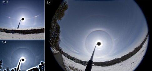
Sometimes odd radius halos come day after another. In April 1987 I observed three consecutive days of odd radius halos and in April 1996 Jarmo Moilanen had four days in a row. On both periods there was also one night with moon odd radius halos.
The three displays shown above were seen on successive days in Tampere on the period of 31 March to 2 April this year ( 1 ). Abundant start of odd radius halos may indicate a good year of high cloud halos coming. 1987 and 1996 were the best high cloud halo years in Finland.
Other displays from this spring:
- odd radius by Patrik Trncak in Holesov on 9 April
- odd radius by Patrik Trncak in Holesov on 1 April
- odd radius by Nikita Kulanov in St. Petersburg on 30 March
- odd radius by Jukka Ruoskanen in Kotka on 27 March
- Wegener by Ágnes Kiricsi in Budabest on 27 March
Saturday, 10 April 2010
High sun parhelic circle
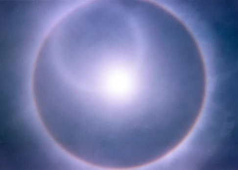
There are not much around photos of parhelic circle that fits inside the 22° halo. Here is one, seen over La Silla astronomical observatory in Chile on 27 January 1990. Sun is at 79 degrees elevation. Damien Hutsemekers, who took the photo, wrote also a report of the display ( 1 ). See some more photos ( 2 ).
Friday, 9 April 2010
Possible new arc from Moilanen crystals
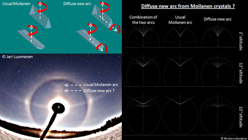
I would like to share some thoughts about a possible new arc. This arc seems to be present on the two observations of Moilanen arc at high source elevation from Jari Luomanen ( 1 ) and Marko Mikkilä ( 2 ). It appears as a diffuse glow below Moilanen arc. This arc can be simulated using any crystal producing Moilanen arc like 34deg prism pointing up (which is not aerodynamically stable) or crystal plates twinned at 34deg (which does not look like a possible twinning) tumbling with large angles along their horizontal axis. As a consequence, this new arc does not help a lot on identifying what crystals cause Moilanen arc.
At lower source elevation, the new arc would mix with the usual Moilanen arc so it is difficult to make the distinction between the two arcs. The main difference is that usual Moilanen appears as a hollow “V” while new arc would be more like a solid wedge. This new arc could be responsible of some appearance of the Moilanen arc when it appears as diffuse ( 3 ) compared to more usual sharp arc ( 4 ).
To draw a parallel, the usual sharp Moilanen is a bit like the upper sunvex Parry arc while the new arc is more like the upper tangent arc. To the extremes, if the crystals take all the rotational angles, there would be a lower component like the lower tangent arc, or if the source is very high, there would be a complete circle like the circumscribed halo.
More observations are needed to confirm the existence of this arc especially at high source elevation when it is clearly separated from usual Moilanen arc, so monitoring about this possibility is encouraged!
Nicolas Lefaudeux
Wednesday, 7 April 2010
Liljequist parhelion does not exist
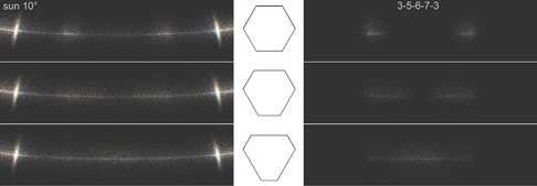
Changing crystal shape causes surprising behavior with Liljequist parhelion, casting doubts on its identity as a halo form. Look at the simulations above, larger image opens by clicking.
I have simulated (software: HaloPoint2.0) the anthelic side of the plate parhelic circle with three crystal shapes. On the left are all rays, on the right only the 3-5-6-7-3 rays that I have often referred as the main contributor to the Liljequist parhelion. But the shape of light stripe created by the 3-5-6-7-3 rays depends on the crystal shape. This means that the definition of the Liljequist parhelion becomes so murky that we might as well forget about it; 3-5-6-7-3 rays are just rays that light the parhelic circle, nothing more.
The other ray that I have mentioned of being responsible for the Liljequist parhelion is the 3-5-6-7 ray. Its product does not change with crystal shape, but it is probably too weak alone to produce any visible brightening on parhelic circle. I think it was me who originally brought up the Liljequist parhelion. I apologize for the mess. I guess we should let go of Liljequist, but it has been around for a while, so that may be easier said than done.
Tuesday, 6 April 2010
Reflection subsun, Salt Lake City
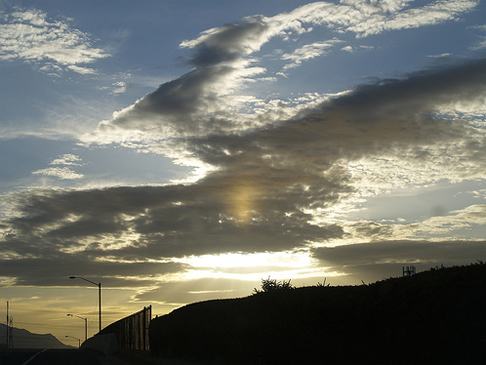
Three earlier observations of the reflection subsun are known, two of which have been shown in this blog ( 2 - 3 ).
Thursday, 1 April 2010
Halo display from Ghana
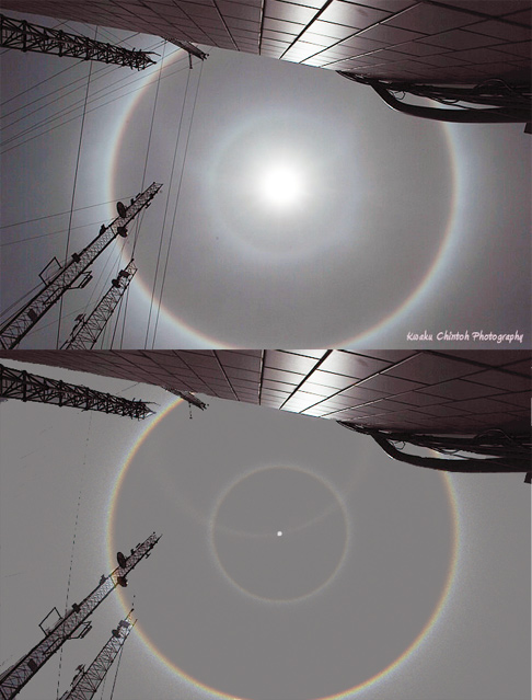
For a change a display from Africa. This was see in Accra, Ghana, on 10 March this year. The photo was taken by Kwaku Chintoh.
Sun is at 75.5 degrees elevation. The two sun concentric halos are rather 9° column arc and circumscribed halo than 9° and 22° halos. That is because of their sharpness - circular halos from randomly or very poorly oriented crystals are expected to be more diffuse. There is also parhelic circle.
In the simulation column oriented prismatic and pyramidal crystals were used. Pyramid crystal tilts are 7 degrees. Simulation was made with HaloPoint2.0 -software. Parameter-file is available ( 1 )
