Showing posts with label Halo information. Show all posts

Monday, 30 May 2011

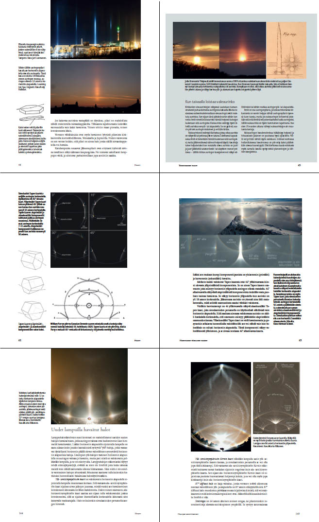
New book on halos


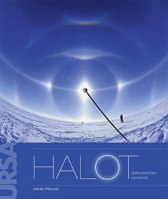
The Finnish Astronomical Association URSA has just published a new book on halos by Marko Riikonen. This book combines the latest halo science with stunning images from all around the world.

Spanning 168 pages, the book presents, illustrates and analyses all the known (and the less well known!) halo forms in great detail. In addition, the newly made discoveries and methodologies concerning spotlight displays are discussed in depth. Many historical displays are also included as a reference. Particular care has been put into preparing the beautiful computer simulations that are used to explain the ice crystal populations behind each display.

The variety of the images is striking and Riikonen has obviously spent a lot of time in finding great examples. Luckily the quality of printing matches these images: I have rarely, if ever, seen a print job this good. Even the faintest halos can be distinguisted in the images.

As Riikonen is a long-time expert in the field, the substance of the book is solid and provides everybody from beginners to experts with new insights about halo science. Being such a significant contribution to the field of atmospheric optics one can but hope for a quick release of an English language edition.

A few select pages can be previewed online (1). Publisher information (2).

Riikonen, Marko (2011) Halot. Jääkidepilvien valoilmiöt. [Halos. The optical phenomena of ice crystal clouds]. Tähtitieteellinen yhdistys URSA ry, Helsinki.

Sunday, 9 January 2011

Hollow columns halo simulation

I wish you all a very happy year 2011, may it be rich in halos and celestial wonders!

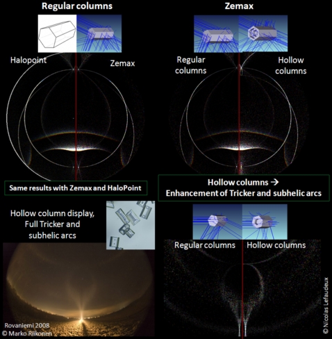
I ran some simulation of halos created by hollow columns. Usually, hollow columns are considered to be poor halo makers, reducing the probability of getting rare arcs. I have simulated hollow columns display using Zemax.

Zemax is commercial software used for optical design. Its primary purpose is design and optimization of optical systems. It allows only static simulation, but I wrote a few macros to simulate halos. The main advantages are that you don’t need to compute yourself all the optics laws, just to concentrate on the halos, and it is very flexible software. I have been able to simulate displays from twinned and complex crystals. Its main disadvantage is that it is very slow compared to dedicated software like Halopoint. I have compared the two software and they give the same halos, so the optics inside is really the same. Crystals used to simulate hollow columns keep their crystalline faces for the hollow parts. In real crystals, the holes appear to be more rounded and smooth. The halos simulated are so from ideal hollow columns. Simulation shows that, quite unexpectedly, hollow columns strongly enhance complex arcs in the anthelic direction. For instance, Tricker and subhelic arcs are much more prominent than with regular columns. Marko Riikonen pointed out a display with samples showing lots of hollow columns that had strong Tricker and subhelic arc. Simulations with hollow columns are quite consistent with the display.

I still don’t really figure how these complex raypaths can have increased probability with hollow columns, but simulations definitely show it.

Nicolas Lefaudeux

Tuesday, 6 July 2010

Suggestion of observation: possible spurious arcs from Moilanen crystals

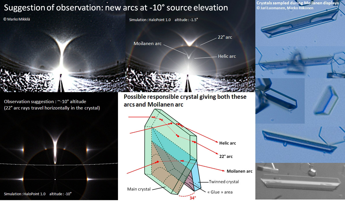
Here is an observation suggestion for next winter. Marko Mikkilä photographed possible new arcs during winter 2007-2008 ( 1 ). Source elevation was -1.5°. Different processing shows them as not only 22° arcs but also new helic arcs.

Some twinned crystals allow creating both similar arcs and Moilanen arc so these arcs could be spurious arcs from Moilanen crystals. Such twinned crystals are present in small amount in samples from Moilanen display. I have put the best images in the main picture. The crystals seem to be two twinned plates with a glue area in between them. Even few of these crystals could give significant Moilanen arc as the ray path is extremely efficient, even more efficient than parhelia ray path (for a plate crystal, rays go mostly in the helion, then in the left/right parhelia/subparhelia and parhelic/subparhelic circle while almost all the rays entering such twinned crystal go in the Moilanen arc (not in the helion)). The 22° arcs would be from rays entering and leaving the small upper tilted prism faces (with total internal reflections in between). The helic arc is mostly from total internal reflection on the small upper prism face.

Some reasons also tend to show that the actual fall orientation of such crystal is with the prism pointing up (and not pointing down like it was thought before).

If this is true, we can deduce that best configuration to see these arcs again is with source elevation around -10°. In this case, 22° arcs rays travel horizontally inside the crystal and so are more likely to exit (as the main habit of the crystals seems to be long needles), helic arcs should also be stronger, and tangent arc is narrow (so well separated from these arcs). However Moilanen arc should be difficult to distinguish from subsun and divergent light pillar.

For similar lower arcs, the best configuration would be source elevation around 10°. However lower arcs are less likely because of the “glue area” messing with the basal faces for total internal reflection.

It would be really interesting for people who have the opportunity to try to get other observation of these arcs next winter. They should be most visible at source elevation around -10° and vanish quickly for positive source elevation. If these arcs are spurious arcs from Moilanen crystals, it would definitely help finding the responsible crystals.

Nicolas Lefaudeux

Monday, 10 May 2010

Simulations on the possible new arc from Moilanen crystals


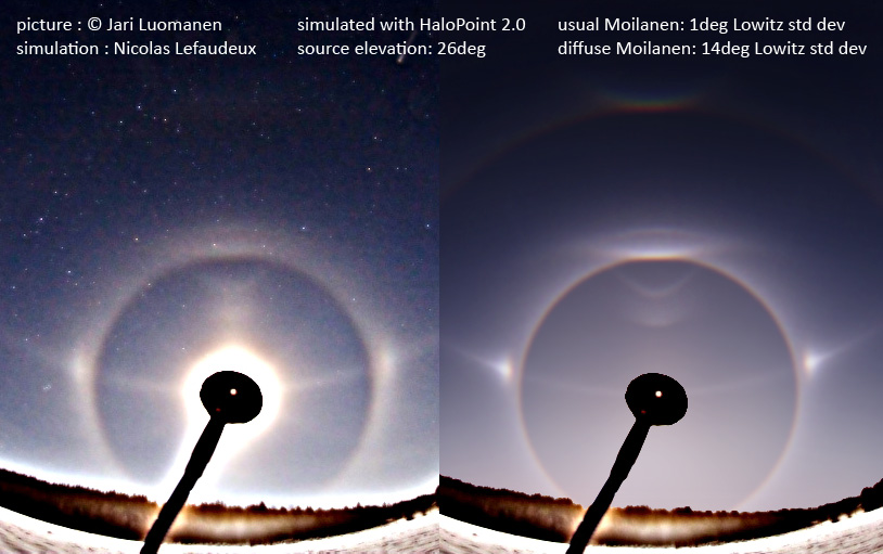
Here are some simulations to follow up with the possible new arc from Moilanen crystals ( 1 ). As suggested by Marko, I did some “photo quality” simulations with the two Moilanen arcs using Jukka Ruoskanen software. The Moilanen crystals are simulated using 34deg prisms pointing up.
First I simulated Jari Luomanen’s picture ( 2 ) which shows best the two arcs. I found that two Moilanen population tumbling with 1° and 14° deviation matched well the display.

Then I tried to compare two low source elevation displays from Marko Riikonen ( 3 - 4 ),and Milan Osecky ( 5 - 6 ). I simulated them with the same populations as the one I found from Jari Luomanen picture (1deg and 14deg standard deviation tumbling angle). The differences between the two populations are pretty subtle at this low source elevation. They are mostly in the shape of the outer edge of the Moilanen arc and in aspect which can be either hollow or solid. New arc has a more solid and curved edge. Although it is difficult to know for sure, I think the two pictures show the two different arcs.

Finally, I did some simulations that shows how one arc becomes another when the tumbling angles are increased, and for different source elevations ( 7 - 8 - 9 - 10 ). The limit between the two arcs would be somewhere between 8 and 16deg tumbling angles. The amount of crystals is kept constant in the simulations so brigthness can be compared. The two arcs vanish quickly when source elevation is increased. With the tumbling angles used (up to 64deg standard deviation), no lower component appears for the new arc.

Nicolas Lefaudeux

Tuesday, 13 April 2010

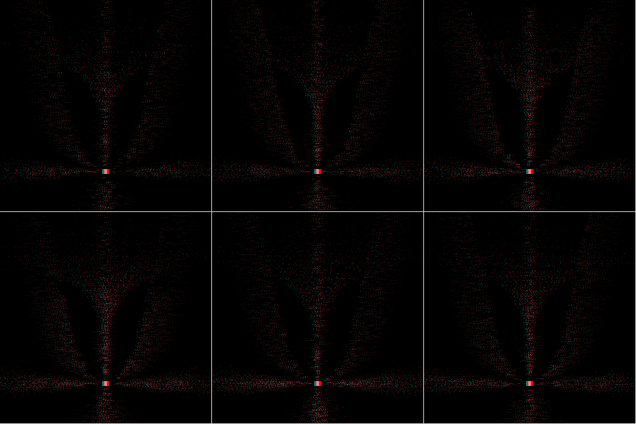
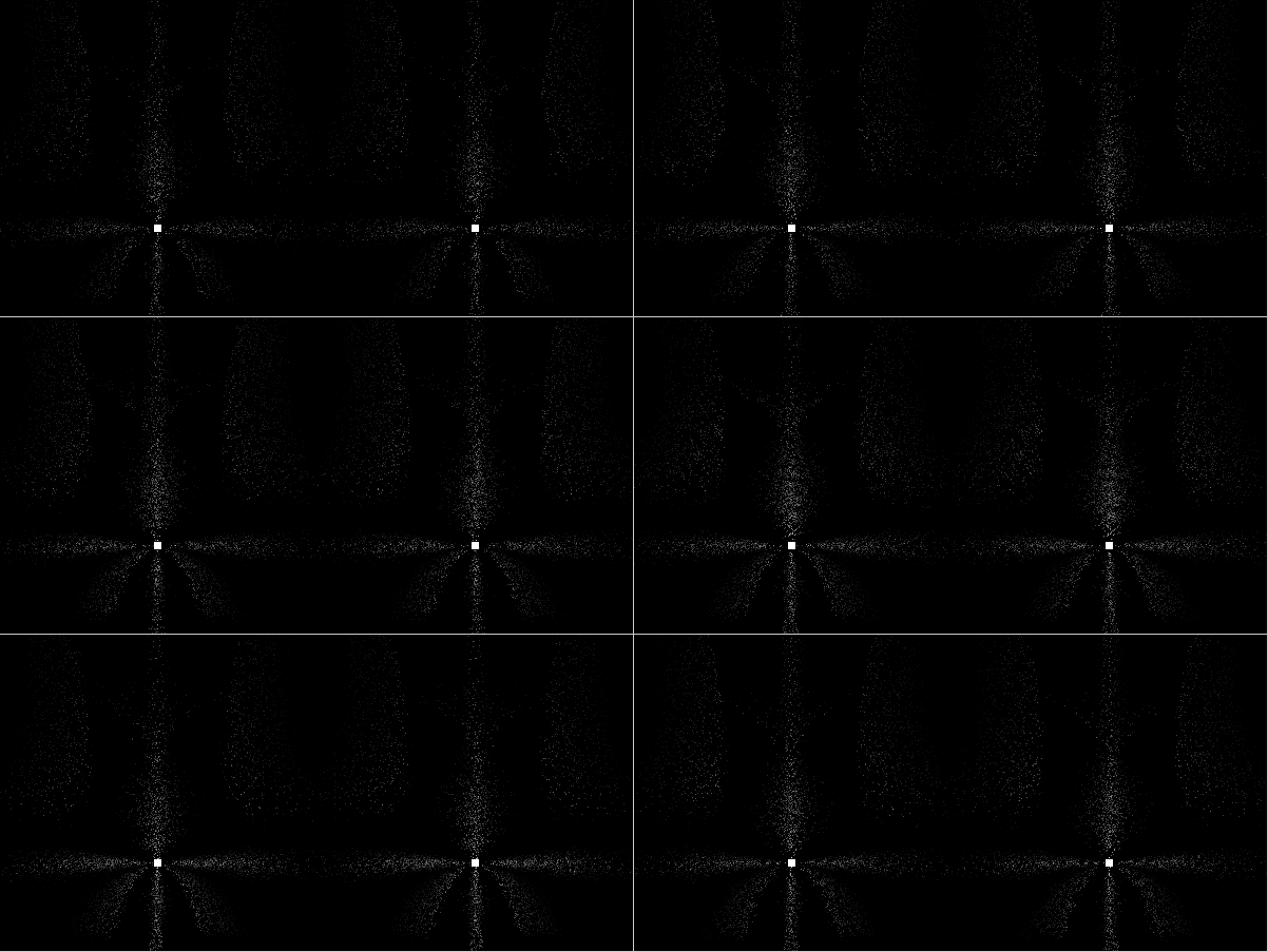
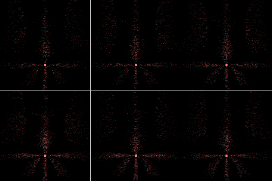
An animated stereo simulation of streetlight halos

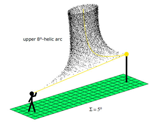
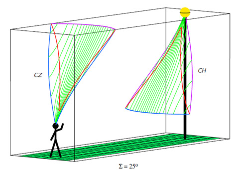
For quite a long time I was wondering how halos in nearby ice crystals, especially when caused by divergent light, are perceived spatially. The AKM halo meeting at the Sudelfeld, Germany in January 2010 has intensified this interest once more, and I tried to capture some stereo pictures with two cameras on conventional slide film. Unfortunately, the results were not as convincing as expected, and there was no further opportunity for me to watch an actual display this season. So I decided to do some computational work instead. I started with the analytical calculations of halo surfaces by Walter Tape ( 1 ) and was curious to see what would come out for two eyes instead of a single observer. The (at least for me) surprising answer was that there should be no stereoscopic depth impression for all the halo surfaces (two Minnaert cigars starting at the lamp and ending in the individual eyes, and so on), they simply appear pinned to a plane through the lamp perpendicular to the direction of sight. This holds true even for the “eye-connected” halos such as the 22° ring or parhelia. This was an unsatisfying result, since I knew from observations during the halo meeting that there is a certain spatial impression in an ice crystal display, especially for the tangent arcs that appear partially much closer to the observer than the lamp. How can this puzzle be solved?

I suggest the following explanation: The ice crystal halo display is not made simply from idealized halo surfaces (or, more general, from an intensity field in space which takes into account all the subtle intensity variations along parhelia, tangent arcs, and so on) rather than from individual crystals that fall down or drift around in space and sample the intensity field pointwise along their trajectories. These crystals are real physical objects and should be perceived stereoscopically at their actual position, if being illuminated externally at equal brightness for each eye. But in case of a streetlight halo they deflect light by themselves to the observer according to the intensity field which lies stereoscopically flat around the lamp. Thus, especially crystals near to the observer should not appear at equal intensity for both eyes. But as long as both eyes receive light without any large difference in intensity the crystal should be perceived at its actual position and not pinned to some plane in the lamp’s distance, and so we get the stereoscopic depth impression of the halo display. This also implies that on a long-exposed stereo photo all contributions form individual crystal trajectories should be averaged, which would lead to a smooth and stereoscopically flat image of the intensity field.

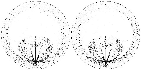
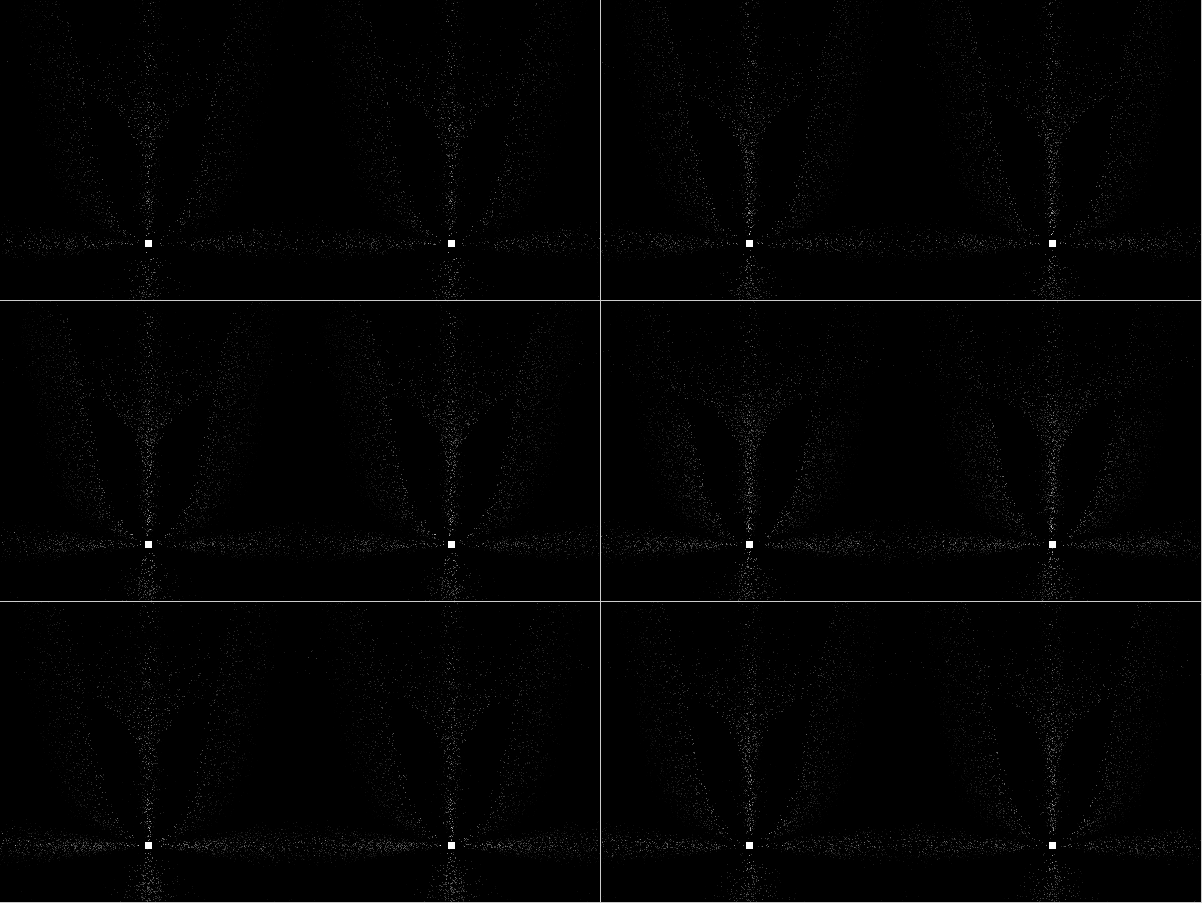
At this point, I had the idea of an animated simulation. Spatial perception is still not fully understood physiologically, and there might also be an influence of dynamic effects from the moving crystals as well. So some kind of stereo animation should be the suitable representation of the problem, and then we can leave the interpretation work to the brain just like in a real display. I started the computation with typically 200000 random crystal positions in a cube between observer and light source that were tracked for 100 time steps. From one step to the next the crystals move a small distance downwards (when reaching the ground, a new position is generated to prevent from loosing the crystals). From geometry, it is quite easy to calculate the intensity for different halo species if the intensity field is provided as some look-up table or analytical fit. This is done separately for each eye. The images linked below show the results for cross-eyed viewing (left image on the right side) and as anaglyph (left image red).

( 2 - 3 - 4 - 5 )

The included halo species are super/sublamps, 22° super/subparhelia, 22° parhelia, and 22° tangent arcs. The distance observer-lamp (in horizontal projection) is 10 m, the lamp elevation is +5° for the first and –5° for the second series. For the first simulation, the field of view corresponds to a 28 mm lens on 35 mm film (cropped to a square area), for the second it corresponds to 20 mm. The histogram had to be cropped at the white edge and the gamma value was increased as well since the original images that were normalized with respect to the brightest pixel would appear much to dark.

There are some simplifications in the model that I don’t want to conceal: No colour dispersion for refraction halos was taken into account, all calculations were done with a fixed index of refraction. Diffraction and defocus blurring were also neglected, each crystal is assigned to a single pixel (but more than one crystal can contribute to the brightness information of one pixel). The intensity ratios between the halo species were set arbitrarily and are not determined by a predefined set of crystals with certain orientations, aspect ratios, and so on. A subtle matter is that remaining degrees of freedom (such as the rotation angle around the vertical axis for parhelia oriented crystals) are already averaged by taking the intensity from a look-up table and not assigning these degrees of freedom to the simulated crystal the same way as it was done with the spatial coordinates. Otherwise the computation time would have increased dramatically. So I did not simulate individual crystals in this sense, or otherwise I have to assume that they are spinning around their allowed axes at quite a high speed in order to do the averaging.

Nonetheless, it can be seen quite nicely from the animations that eye-connected halos (parhelia, upper tangent arc for positive lamp elevation, “super”parhelia at negative lamp elevation…) near their classical positions – when crystals close to the observer are involved – seem to pop out of the screen and show a distinct stereoscopic depth impression.

Kind regards,
Alexander Haußman
Saturday, 13 March 2010

New halo simulation program, HaloPoint 2.0, released


In numerous entries of this blog there are halo simulations made with "a simulation software by Jukka Ruoskanen". The software has been under development for the past couple of years and has now reached the point where it is ready enough to be published. The software, HaloPoint 2.0, has its own webpage from which the software as well as it's user manual can be downloaded.

The software package is a zip-file. Simply extract it into a suitable directory and keep the two components of the software, HaloPoint.exe and Simulation.dll, always in same directory. The software runs in computers having Windows operating system (tested in XP and Vista). Also a .NET Framework 1.1 is required, which is already installed in most computers, but in case it is missing it can be downloaded for free from Microsoft pages.

In software homepage there are simulation examples together with parameter files so that getting started with the software is easy. In addition to the examples it is advisable to take a glance at the user manual so that the various features of HaloPoint 2.0 can be utilized.

Hope you'll have fun with it.

Wednesday, 27 January 2010

Forked Pillars and Helic Arcs

I expanded the "Forked Pillars and Helic Arcs" article. As before, it is on my page ( 1 ). For observers probably the most intriguing addition to the article is the suggestion to watch for a zenith ring. With hindsight the idea of a zenith ring is painfully obvious.

Walt Tape

Thursday, 13 August 2009

Lars Gislén's streetlight halo simulator

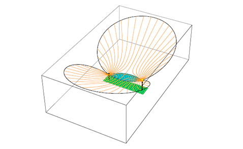
The halo application simulates streetlight halos ( 1 ). It can handle plate and column crystals as well as Parry oriented crystals. It can generate stereo pictures both for viewing in a stereo viewer or directly with "crossed yes". The application can also generate a data file with the 3D location of the crystals involved in the display that can later be viewed in a separate 3D viewer.

There is a short PDF manual together with an explanation of how the halo is simulated. Finally you can download the (rather messy) Java source code.

Detailed (large recycle value) halos may take the order of one hour to simulate. With the least detailed (recycle = 1) setting it takes much shorter time.

There are two implementations of the halo applications, one for Macintosh OS X 10.4+ and one for Windows. A Windows machine may need to download the Java Runtime Environment (JRE) that is available free ( 2 )

Text: Lars Gislén

Thursday, 9 July 2009

119 pages of streetlight halos

The days are shortening and winter is coming soon. What a better way to get pumped for the upcoming diamond dust season than reading Walt Tape's 119 page treatment on spatial halos. New effects like superparhelic circle await for their discoverers. About half of the contents is the old stuff that you may have read already, but Walt has made some changes, so it is not bad idea to go through those parts as well.

Click on the image to go Walt's page to download it.

Friday, 13 March 2009

Halo Meeting 2009

There is less than half a year left until Halo Meeting 2009. The "official" registration form ( 1 ) has been added to our website, and also important information about the costs and the method of payment. Please, read these pages carefully, fill in the form, and keep it in mind that the deadline for both registering and paying the fee is 31 May 2009. You will notice that our homepage has moved to a new address – this is due to regular problems with the previous server ( 2 ).

We are looking forward to hosting this event very much.

Sunday, 1 March 2009

More light on spatial halos

Streetlamp halos with their spatial form can be memorable experiences for the viewer. Yet, we know rather little of them. But now this is changing as Walt Tape has taken a look at several spatial halos in four articles ( 1 ). There are numerous revolutionary insights and a whole new nomenclature is created. And best of all, articles can be read also by mathematically less gifted as there are hardly no equations.

Tuesday, 16 December 2008

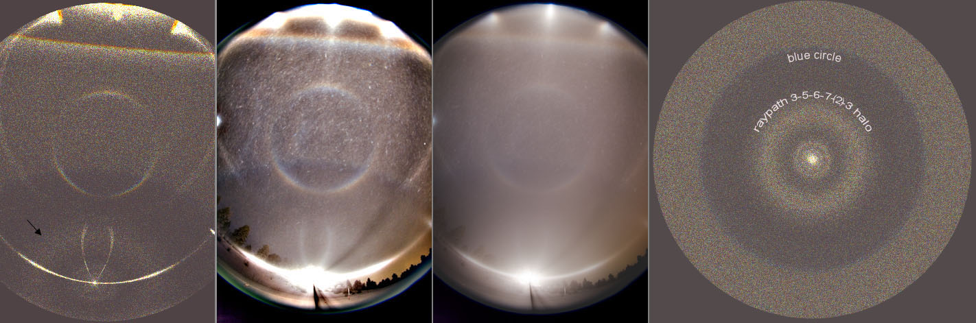
Circular subanthelic halo from 3-5-6-7-(2)-3 raypath

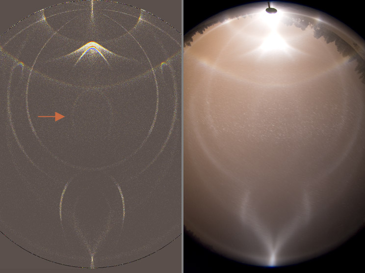
The subhorizon photos of 7/8 December show what seems to be part of a diffuse circular halo surrounding the subanthelic point. Similar effect can be simulated with random oriented crystals (arrow in the simulation on the left). It arises from raypaths 3-5-6-7-3 and 3-5-6-7-2-3, which in plate crystals make respectively the Liljequist and sub-Liljequist parhelia.

The simulation on the right provides a 180 degree view of halos from random orientation centered around the subanthelic point. The bright dot is the subanthelion. The narrow small radius halo is from raypath that I have not checked. It seems to disappear if the crystals deviate even a little from regular hexagonal shape. Then there is the diffuse 3-5-6-7-(2)-3 subanthelic halo and blue circle.

Finally, a note on the Parry crystals used in the simulation on the left: no triangles this time, regular h/d 1 hexagons were used. Simulations with Jukka Ruoskanen's software.

Monday, 15 December 2008

Blue circle

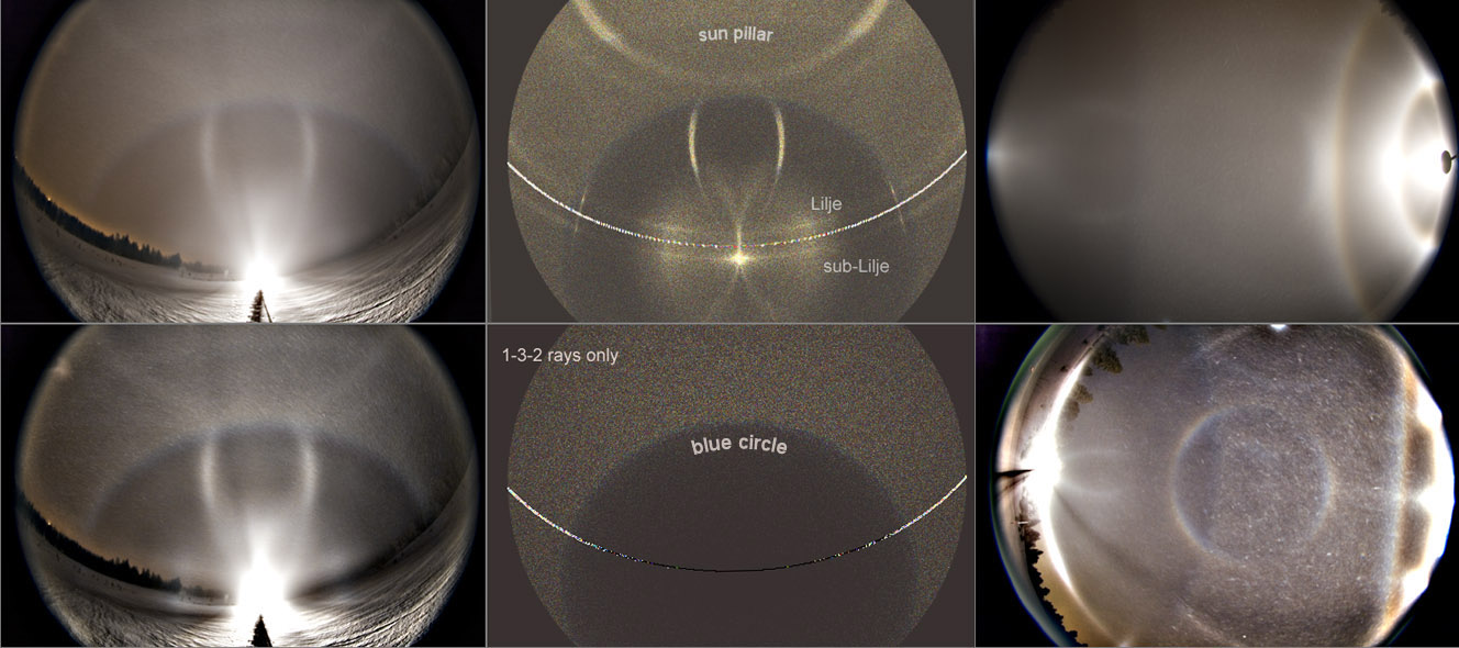
What happens when tilts of the crystals that make blue spot increase? The blue spot starts to elongate vertically, forming eventually a blue circle. It is shown in these images that were taken on 7/8 December night in Rovaniemi.

Simulations in the middle used plate crystal tilts of 90 degrees to make blue circle. In the lower simulation the 1-3-2 rays responsible for blue circle are shown (probably also 3-1-6 rays contributed, but they were not included).

Blue circle is a circle of about 70 degrees radius around the subanthelic point. The intersection of parhelic circle and blue circle is the location of the blue spot. This gives us a practical insight on why blue spot changes position and elongates with increasing sun elevation ( 1 ).

Also other halos are seen in the photos. Some of these are named in the simulations, which are made with Jukka Ruoskanen's software.

Thursday, 11 December 2008

A halo from Parry oriented crystals with raypath 4-8-1

The photo is from last weekends major display. The arrow in the accompanying simulation (Jukka Ruoskanen's program) points to a halo that arises from Parry crystals with raypath 4-8-1 (where 3 is upper face). This arc was found from photos previous winter ( 1 ). Simulations showed then that triangular Parry crystals made it. Same applies to this new case: Parry halos in the display were simulated successfully only with triangular crystals.

Tuesday, 9 December 2008

Subhorizon plate crystal halos

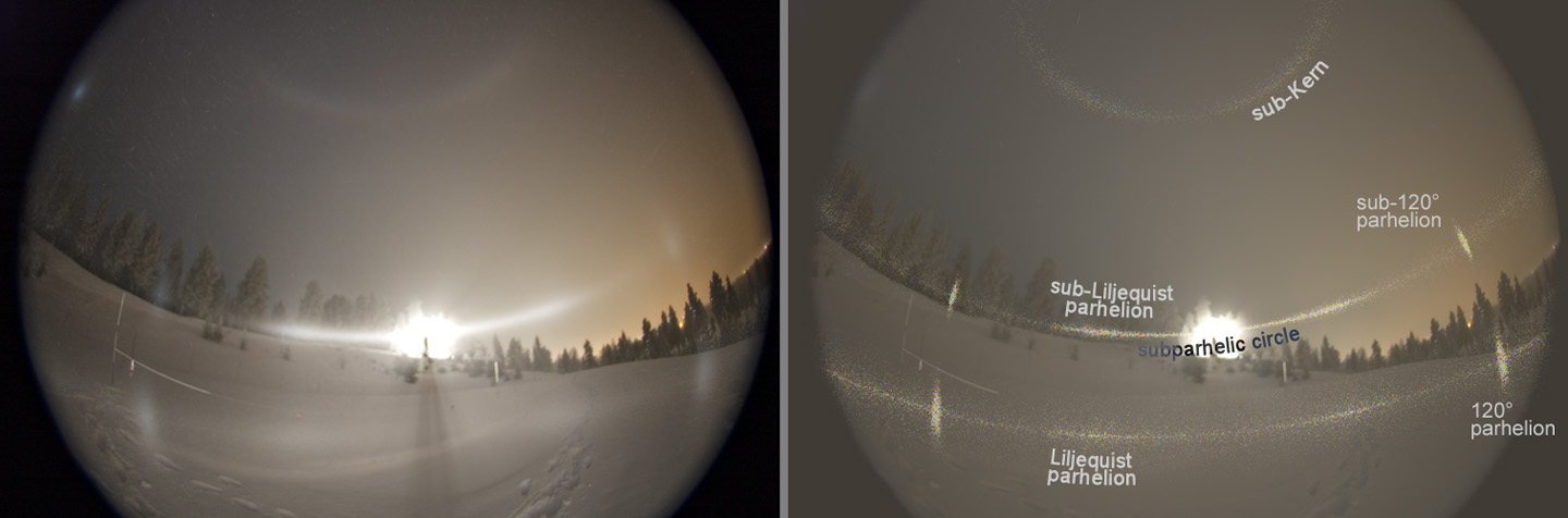
On the night of 7/8 December in Rovaniemi water fog was nucleated to diamond dust by snow machines, and a major display was observed in a spotlight beam for several hours. The photo above is from the end stage when plates dominated.

The lamp is downhill below the horizon (about 11.5 degrees), which shifts subhorizon halos above the horizon. Halos are named in the simulation which is made with Jukka Ruoskanen's program. Sub-Kern and sub-120° parhelia have not been documented before. By other means these are difficult to see. One needs to sit in an airplane which happens to pass through a high quality crystal cloud and sub-Kern is also located so low that one probably is not able be view it from small airplane window.

Crystals used in the simulation were plates which prism faces were allowed to variate freely in size within some limits. This produced the rather uniform stretch of subparhelic circle where sub-Liljequist parhelia are becoming hard to distinguish. Had there been solely regular hexagons in the air, the sub-Liljequist parhelia would have been better defined.

There was also circumnadir arc, which is another new feature. Les Cowley ( 1 ) has more on this and other subhorizon halos in the display.

Sunday, 7 December 2008

Reflected lower sunvex Parry behaviour

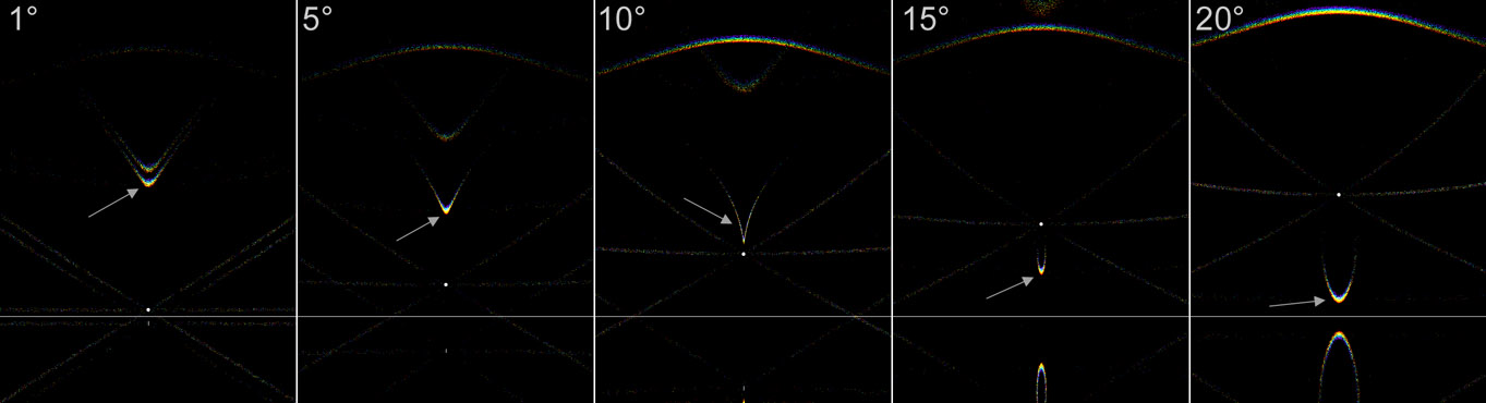
To supplement Les's posting, here is the behaviour of the reflected Parry as a function of sun elevation. At sun elevations higher than about 11 degrees, the halo arc is below the sun. The halo is perhaps easiest understood by thinking of it as a Parry arc of the subsun. At the solar elevations given in these simulations, it stays all the time at 22 degrees above the subsun. So if you know solar elevation, you know also where it is located relative to the sun.

In simulations for 15 and 20 degrees sun elevation also the normal lower sunvex Parry is seen, being as much below the horizon as the reflected Parry is above the horizon. Simulations are made with Jukka Ruoskanen's software.

Friday, 5 December 2008

A peculiar halo on 6 November in Rovaniemi

In the image on the left is Moilanen arc among other halos. On the right is similar looking halo (arrow), but its V is more pointed and it is also closer to the sun, about 7 degrees above it. These are stacked images, the inset image is a single frame showing the same arc (and also a weak Moilanen arc above it).

This halo seems to be what could be called a "reflected lower sunvex Parry arc". It was Walt Tape who suggested this kind of explanation for the arc. I will later add a post with simulations, crystal figures and raypaths. Pictures of the halo were published today in Tähdet ja avaruus magazine in Finland.

*** addition 5 December: see the upcoming posting on Les Cowley's site ( 1 ), which lights up the formation of this arc ***

Thursday, 4 December 2008

Lascar display V

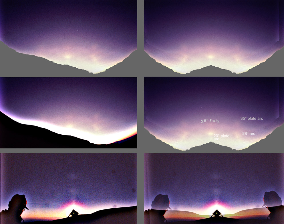
For the very lowest sun elevations there are only two photos, both shown here. Four uppermost images are versions of the same photo, which was the last one taken that day. Because halos have turned reddish, I suspect the sun was already below horizon.

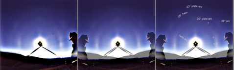
Again a new feature has appeared, the 35° plate arcs. Others are familiar from previous postings.

To avoid wash-out from unsharp masking, ground was removed. For comparison, in the image on the middle left, the ground has not been removed. Same amount of unsharp mask and levels has been applied to both versions.

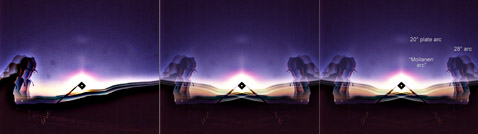
Photos at the bottom are from 1.6 degrees sun elevation (not to scale with upper photos). Two arcs directly above the sun are 20° upper plate arc and "Moilanen arc". From this slide the latter was measured to be 12 degrees from the sun.

Wednesday, 3 December 2008

Lascar display IV

Now the sun elevation at Lascar is 2-3 degrees. The image is four frame stack. 20° upper plate arc is well visible. New feature, "Moilanen arc", has appeared. We observed it visually, it was V-shaped, not like the light mass seen in this photo. Photographing this arc was difficult, because it appeared and disappeared in seconds intervals. Measurements from two slides placed the arc at 10.5° from the sun, which is less than for Moilanen arc. But of course there is uncertainty in that value.

Lascar display III


Continuing the Lascar halos tour. This image gives situation for sun elevation range of 11° to 9°. Image is stacked from four photos and also mirrored version is provided. 23° plate arc is already disappearing high up above the sun, but 20° upper plate arc on the other hand is appearing.

10 years ago we simulated the display with octahedral crystals of cubic ice and traditional pydamidal crystals. Octahedral crystal gives halos only at 28° and 19° from the sun. It was a good candidate for simulating because many features in photos from different solar elevations fell in place with it.

Among other things these simulations predicted that the 20° upper plate arc would be actually composed of two arcs, the other one being 19° upper arc... But there are still too many unexplained features in the display to trust our model, one being the fake 18° plate arcs.